This is a two tone door buzzer, which is an electronic buzzer
types,but them has melodic sound than the general electric bell. Which
many people have seen the two tone bell sounds from other electronic
journals.
But they are circuit that made no who apply them, since Problems three reasons:
1.First, while do not press a switch, the circuit also still have a lot of current consumption around up to several tens of milliamperes.
If will make on-off switcher, a power supply of circuit will must add other one switch individually. When we will press the buzzer we must press the other switch before, then when press completely the buzzer switch, we must close power switch again. To set to application as begin.
2. Secondly, the output sound is real two level. But the sound is vibrant and clear.
3. Thirdly, Suppose that solving the problem on-off switch,with replace an old battery with a DC adapter to circuit.
But the providing the power supply to circuit all the time that may making IC has heat and fast damaged, because those circuit use IC as the sound generator and they have more many cost than transistors.
So some companies ever produced a two tone buzzer kit to sell. But now out of production to Because of Problems mentioned above.
But for this two tone door buzzer that I would like to introduce you build them, which as circuit are designed become to solve all those.
If you do not press the buzzer switch, the circuit will not use the Low power consumption, by not must have on-off switch individual. And though while press the buzzer switch, the circuit will use low current so long time apply though is use by the normal battery.
Another issue, the circuit is designed to use all the transistors. In addition will clear, melodious and resonant voice. And creating cost savings as well. Because the transistors has very cheaper than ICs.
The working principle of circuit
In circuit diagram as Figure 1 will see that we use both transistor are connecting as the oscillator circuit on multi vibrator form. To crease a square wave signal then send to amplify in the next transistor before,to provide the signal high up then enter to the speaker.

Figure 1 the circuit diagram of the two tone door buzzer using transistors.
Observe the circuit to generate the sound. Sound frequency is determined by the value of Resistors and Capacitors. Here we use the C-0.01uF is constant.
So if we change the value of Resistors, Frequency of sound will go to change. Which Resistors in circuit has two set are R-33K quantity = 2 pcs. And Resistors R-50K other one.
While when we press switch, which is the pushbotton switch, current will flow through separated into two ways.
First way, flow through Diode-D1 go to charge in the capacitor-33uF 10V and while is also supply the current to Collector lead of both transistors.
Final ways, current will flow through diode-D2 in to common joint of R-33K to bias to base lead of both transistors.
In while both transistors will can oscillate, because have fully bias and frequency that get from usage this resistor-33K will be 2,200 Hz amplify out of speaker into high frequencies.
When we release the switch will no current flowing through both diode but will also has some current that still charge in capacitor-33uF 10V.
Which it will discharge out of the power supply to the oscillator circuit. But in while current in the base circuit will must pass both resistors-33K and 50K are mixed into 83K. When they have high resistance cause low frequency, from Calculated to be approximately 800 Hz. And This capacitor of 33uF 10V will fully discharge within time about 1.5 second. The oscillator will stop working,the speaker will go silent.
I concluded that, when press switch will be sound at frequencies of 2,200 HZ
Switch is released, it will sound frequency of 800 Hz is about 1.5 second. So, we will have the two tone door buzzer as you need.
The building and application.
This circuit have a printed circuit board copper foil track layout of this project. (actual-size) as Figure 2, For building also still same general circuit (as Figure 3) is put a low components before example: Resistors, Diode, Capacitors, Transistors sequence.

Figure 2 Actual-size,Single-sided PCB layout

Figure 3 the top bottom components layout.
The speaker is used with size of 2 inchs 8 ohms 0.25 W to The compact But it applies to the other sizes.
This circuit use 9 volts power supply, All resistors use size ¼ W, switch use pushbutton types,and transistors; use number C1815,C828, or others NPN transistors. other parts see in circuits.
But they are circuit that made no who apply them, since Problems three reasons:
1.First, while do not press a switch, the circuit also still have a lot of current consumption around up to several tens of milliamperes.
If will make on-off switcher, a power supply of circuit will must add other one switch individually. When we will press the buzzer we must press the other switch before, then when press completely the buzzer switch, we must close power switch again. To set to application as begin.
2. Secondly, the output sound is real two level. But the sound is vibrant and clear.
3. Thirdly, Suppose that solving the problem on-off switch,with replace an old battery with a DC adapter to circuit.
But the providing the power supply to circuit all the time that may making IC has heat and fast damaged, because those circuit use IC as the sound generator and they have more many cost than transistors.
So some companies ever produced a two tone buzzer kit to sell. But now out of production to Because of Problems mentioned above.
But for this two tone door buzzer that I would like to introduce you build them, which as circuit are designed become to solve all those.
If you do not press the buzzer switch, the circuit will not use the Low power consumption, by not must have on-off switch individual. And though while press the buzzer switch, the circuit will use low current so long time apply though is use by the normal battery.
Another issue, the circuit is designed to use all the transistors. In addition will clear, melodious and resonant voice. And creating cost savings as well. Because the transistors has very cheaper than ICs.
The working principle of circuit
In circuit diagram as Figure 1 will see that we use both transistor are connecting as the oscillator circuit on multi vibrator form. To crease a square wave signal then send to amplify in the next transistor before,to provide the signal high up then enter to the speaker.
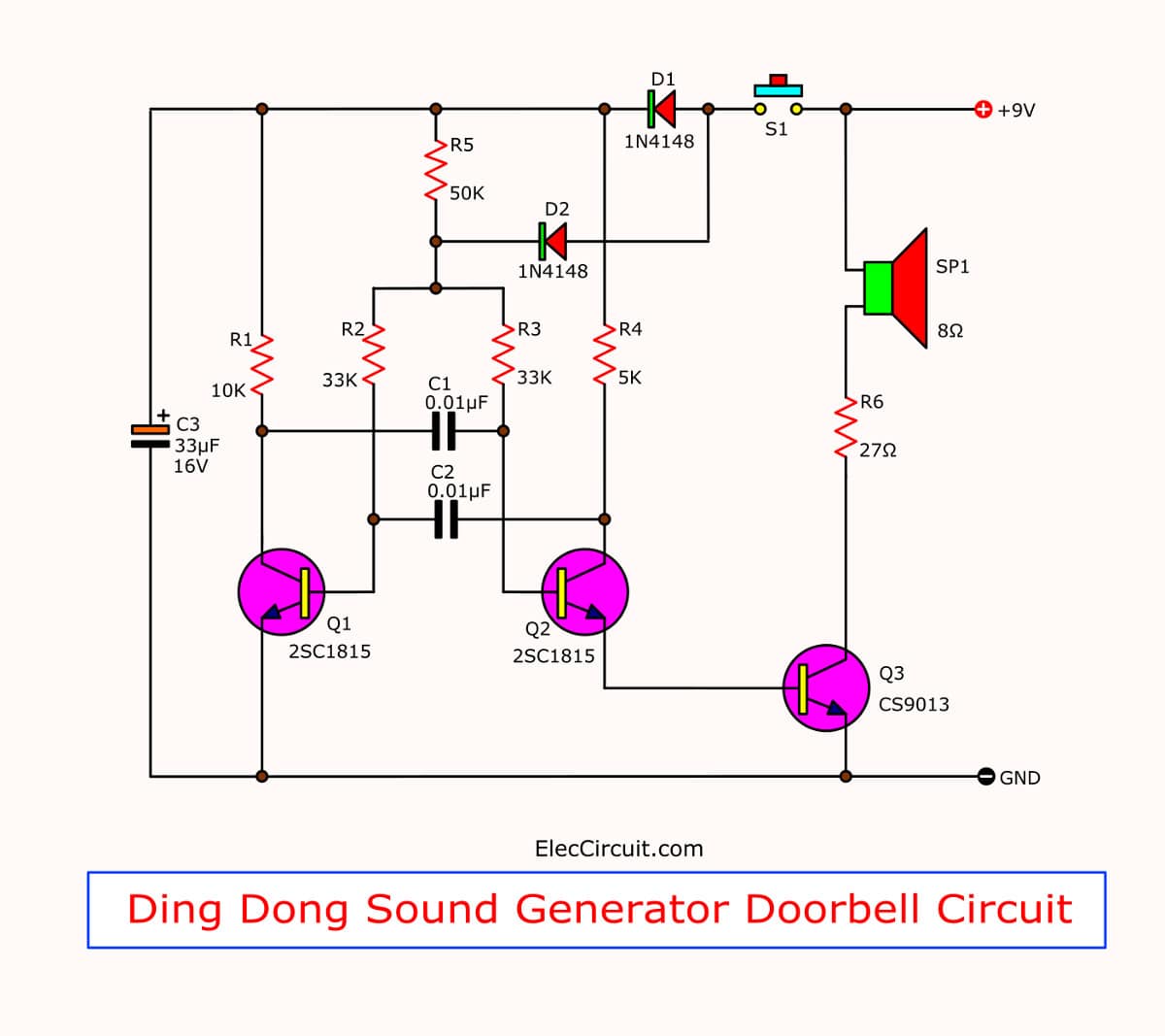
Figure 1 the circuit diagram of the two tone door buzzer using transistors.
Observe the circuit to generate the sound. Sound frequency is determined by the value of Resistors and Capacitors. Here we use the C-0.01uF is constant.
So if we change the value of Resistors, Frequency of sound will go to change. Which Resistors in circuit has two set are R-33K quantity = 2 pcs. And Resistors R-50K other one.
While when we press switch, which is the pushbotton switch, current will flow through separated into two ways.
First way, flow through Diode-D1 go to charge in the capacitor-33uF 10V and while is also supply the current to Collector lead of both transistors.
Final ways, current will flow through diode-D2 in to common joint of R-33K to bias to base lead of both transistors.
In while both transistors will can oscillate, because have fully bias and frequency that get from usage this resistor-33K will be 2,200 Hz amplify out of speaker into high frequencies.
When we release the switch will no current flowing through both diode but will also has some current that still charge in capacitor-33uF 10V.
Which it will discharge out of the power supply to the oscillator circuit. But in while current in the base circuit will must pass both resistors-33K and 50K are mixed into 83K. When they have high resistance cause low frequency, from Calculated to be approximately 800 Hz. And This capacitor of 33uF 10V will fully discharge within time about 1.5 second. The oscillator will stop working,the speaker will go silent.
I concluded that, when press switch will be sound at frequencies of 2,200 HZ
Switch is released, it will sound frequency of 800 Hz is about 1.5 second. So, we will have the two tone door buzzer as you need.
The building and application.
This circuit have a printed circuit board copper foil track layout of this project. (actual-size) as Figure 2, For building also still same general circuit (as Figure 3) is put a low components before example: Resistors, Diode, Capacitors, Transistors sequence.
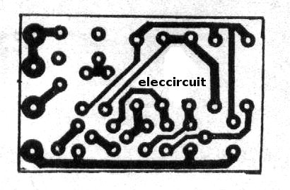
Figure 2 Actual-size,Single-sided PCB layout
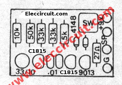
Figure 3 the top bottom components layout.
The speaker is used with size of 2 inchs 8 ohms 0.25 W to The compact But it applies to the other sizes.
This circuit use 9 volts power supply, All resistors use size ¼ W, switch use pushbutton types,and transistors; use number C1815,C828, or others NPN transistors. other parts see in circuits.
No comments:
Post a Comment