This is simple circuit that we makes in hobby time or toys for my
son but really uses. It will have sound alarm when morning like a
normal clock alarm with lighting sensor same clock. We use a IC-4011
CMOS only one and a few components also can generate pulsating tone
like a general clock.
How This Circuit works.
As Figure 1 This circuit use the IC-4011 quad nand gate as main of circuit, it includes for separate positive logic nand gate on a single silicon chip. In circuit diagram consist of an oscillator circuit in astable multivibrator 2 set.
First set include of IC1a and IC1b, then second set include of IC1c and IC1d.

Figure 1 is completely morning alarm with sunlight.
A R1 is LDR (Light Depended Resistor) or photoresistor which is a resistor type. The resistance of a photoresistor changes with the light intensity to strike them.
If no light strikes it.
This resistor R1 may have high resistance rises between 500K to 600K. And if have normal light (Common Fluorescent light.) The resistance will reduce is about 20K – 30K.
On the condition that LDR is getting light, because of its high resistance to more than the value of R2. The voltage at pin 1 of IC1a will lower half of power supply. This cause first oscillator does not work. So the second oscillator also not works. Therefore without sound out of speaker.
When LDR get light its resistance will reduce and voltage drop across it will reduce making voltage across R2 rises unless more than half of the power supply. It cause the first oscillator working to generate the output frequency.
So this frequency can determine with Resistor R1 and Capacitors C1
Frequency output = F = 1/(2.2R1C1)
Which we use value R1 and C1 as circuit above will get frequency about 4 Hz. At the same time the output of IC1b is state “1” will cause the second oscillator (include with IC1c, IC1d and R4, C2) cause have frequency about 900 Hz.
And if output of IC1b is state “0”, then the second oscillator will not works. The output of IC1d that is the tone burst signal as Figure 2.

Figure 2 the tone burst signal characteristics.
The transistor-Q1 (BC547) and Q2 (BC337) are connected as darlington compound to increase current upper. The resistor-R4 will reduce slightly volume of speaker. If you want to high volume sound you need to change value lower.
The capacitor – C3 (100uF 16V) across between positive and ground of circuit which acts as filter the pulsating voltage into into a steady direct current.
How to builds and application.
We can build this project easily, by solder all components on the perforated board and wiring as Figure 3 , Then you may will install them in the universal box. We drill aperture for LDR and potentiometer to adjust easily light sensitivity.

Figure 3
When will assemble completely this projects. Then check for errors. Next, turns On to apply circuit. And then move LDR to light will hear alarm sound out of speaker.
Next, shade the photoresisitor cause sound stop. That R2 is adjuster light sensitivity of circuit,mean that we can set them to begin working at any light as we need.
As video below we test this in really uses.
The components List.
Resistors ¼ watts 5% (Unless otherwise specified.)
R1———-LDR (change value in range of 20K-600K)
R2———-VR 100K___Trimmer Cermet or Carbon
R3———-1M
R4———-500K
R5———-20K
R6———-20 ohms
Capacitors
C1———-0.1uF 50V__Mylar__________ = 1 pcs.
C2———-0.001uF 50V__ Mylar_______ = 1 pcs.
C3———-100uF 16V___Electrolytic____= 1 pcs.
Semiconductors
Q1———–BC547
Q2———–BC547,BC337
IC1———- CD4011 nand gate cmos
others
9-volts battery with in snap connector.
On/Off switches.
Speaker 8 ohms 0.5 watts
Wires, and others etc.
How This Circuit works.
As Figure 1 This circuit use the IC-4011 quad nand gate as main of circuit, it includes for separate positive logic nand gate on a single silicon chip. In circuit diagram consist of an oscillator circuit in astable multivibrator 2 set.
First set include of IC1a and IC1b, then second set include of IC1c and IC1d.
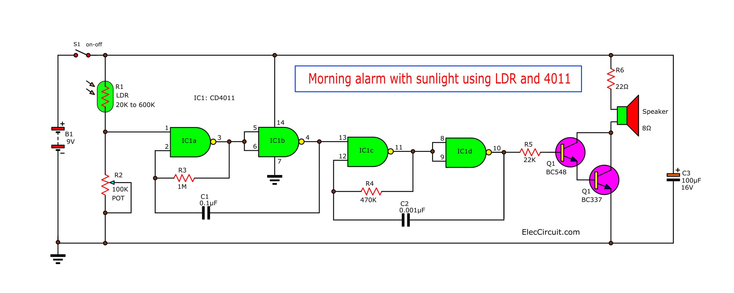
Figure 1 is completely morning alarm with sunlight.
A R1 is LDR (Light Depended Resistor) or photoresistor which is a resistor type. The resistance of a photoresistor changes with the light intensity to strike them.
If no light strikes it.
This resistor R1 may have high resistance rises between 500K to 600K. And if have normal light (Common Fluorescent light.) The resistance will reduce is about 20K – 30K.
On the condition that LDR is getting light, because of its high resistance to more than the value of R2. The voltage at pin 1 of IC1a will lower half of power supply. This cause first oscillator does not work. So the second oscillator also not works. Therefore without sound out of speaker.
When LDR get light its resistance will reduce and voltage drop across it will reduce making voltage across R2 rises unless more than half of the power supply. It cause the first oscillator working to generate the output frequency.
So this frequency can determine with Resistor R1 and Capacitors C1
Frequency output = F = 1/(2.2R1C1)
Which we use value R1 and C1 as circuit above will get frequency about 4 Hz. At the same time the output of IC1b is state “1” will cause the second oscillator (include with IC1c, IC1d and R4, C2) cause have frequency about 900 Hz.
And if output of IC1b is state “0”, then the second oscillator will not works. The output of IC1d that is the tone burst signal as Figure 2.
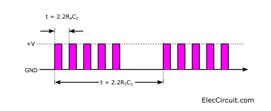
Figure 2 the tone burst signal characteristics.
The transistor-Q1 (BC547) and Q2 (BC337) are connected as darlington compound to increase current upper. The resistor-R4 will reduce slightly volume of speaker. If you want to high volume sound you need to change value lower.
The capacitor – C3 (100uF 16V) across between positive and ground of circuit which acts as filter the pulsating voltage into into a steady direct current.
How to builds and application.
We can build this project easily, by solder all components on the perforated board and wiring as Figure 3 , Then you may will install them in the universal box. We drill aperture for LDR and potentiometer to adjust easily light sensitivity.
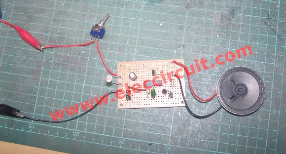
Figure 3
When will assemble completely this projects. Then check for errors. Next, turns On to apply circuit. And then move LDR to light will hear alarm sound out of speaker.
Next, shade the photoresisitor cause sound stop. That R2 is adjuster light sensitivity of circuit,mean that we can set them to begin working at any light as we need.
As video below we test this in really uses.
The components List.
Resistors ¼ watts 5% (Unless otherwise specified.)
R1———-LDR (change value in range of 20K-600K)
R2———-VR 100K___Trimmer Cermet or Carbon
R3———-1M
R4———-500K
R5———-20K
R6———-20 ohms
Capacitors
C1———-0.1uF 50V__Mylar__________ = 1 pcs.
C2———-0.001uF 50V__ Mylar_______ = 1 pcs.
C3———-100uF 16V___Electrolytic____= 1 pcs.
Semiconductors
Q1———–BC547
Q2———–BC547,BC337
IC1———- CD4011 nand gate cmos
others
9-volts battery with in snap connector.
On/Off switches.
Speaker 8 ohms 0.5 watts
Wires, and others etc.
No comments:
Post a Comment