This circuit is a simple siren circuit that use 220V AC as power
supply. It is small size and use a piezo speaker cause use low power and
saving.
How it works
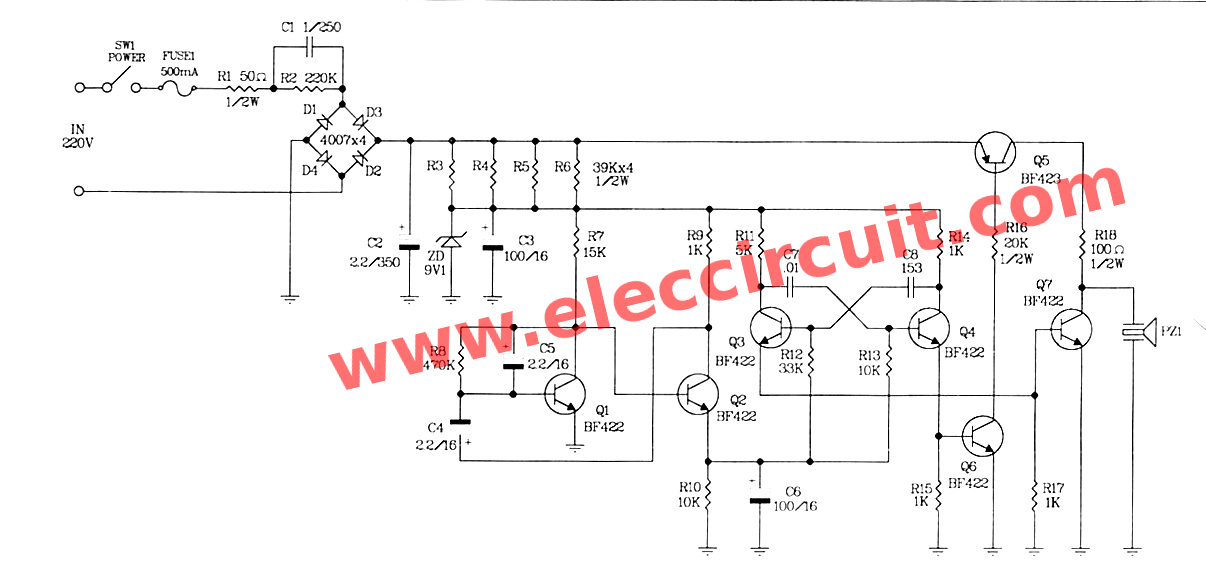
This circuit is shown as Figure 1 which we use power source by reducing AC-voltage of 220 volts down by the resistors-R1, R2 ; the capacitor-C1 act as coupling AC-voltage. Secondly, the current will rectifier into DC voltage by diode bridge D1-D4. And there is C2 function to filter steady DC current.

The some voltage will flow to emitter lead of Q5 and other will is sent to R3-R6 to reduce voltage to ZD1 before, which it will maintain the steady (DC) current regulated supply at about 9.1 volts. The capacitor-C3 will smooth or filter the pulsating voltage from a power supply into direct current.
To begin with press switch-SW1, the 220V AC voltage will reduced into 9.1 volts as power source of this circuit.
Both transistor- Q1 and Q2 are connected to a low frequency generator form, by output frequency depend on R7, R8, R9, C4 and C5.
When begin apply the power supply in to the circuit. The Q2 will works, at the same time C6 will start charge current. While transistor-Q2 is working, C5 will charging until voltage drop across C5 about 0.6 volts.
The transistor-Q1 will begin working cause Q2 stop. Then C4 start charging. At the same time it will pull current from B of Q1, so Q1 stop. Next Q2 will start renew again, Will be this indefinitely. The voltage at E of Q2 will charged to C6 and stop charging according to loop above. While Q2 stopped, C6 is discharged by R10 automatically.
The emitter lead ‘s voltage of Q2. In addition will charge the C6 is also supplied to B of Q3 and Q4. Which they are connected into an astable multivibrator circuit feature.
The operation of this project will start by Assume that the function Q4 (ON), located in the state of saturation and Q3 inactive (OFF). The C7 will be charged until the voltage across it is equal to the voltage of E of Q2.
While the Q2 performance, voltage at C of Q3 will increase, Until equal voltage from E of Q2. R13 serves to determine the size of the base current of Q4. To get the minimum, which makes Q4 can work in saturation.
Therefore it can be seen that when the capacitor-C7 capacitor fully. Q4 is working perfectly and is a state of saturation. And vice versa. When Q3 a state of saturation work. The capacitor-C8, it will keep fully charged, the voltage drop, equal to the voltage of E of Q2.
While Q4 is in the works to make positive of capacitor C8 becomes negative. All this work, will result in Q6 and Q7 working alternately.
When Q6 works, Q5 also works to follow with PZ1. There was a shake-up until it was pitched up. But when Q5 and Q6 stop working, Q7 will work instead PZ1 so gradually stopped shaking and the sound stopped.
How to Assemble this circuit.
Who created this project requires special precautions. It involves AC 220 V directly. First is to start making PCB as Figure 2. which actual-size of Single-sided Copper PCB layout. Making PCB should check the accuracy of the PCB before. Then Assemble parts when examining successfully. As Figure 3 Component layout for the PCB, Should be soldered from the low to the high, and if the device is a terminal. I need to see well before soldering.

Figure 2 The Copper PCB layout.

Figure 3 The component layout.
Testing
We should check for errors before. The external device as Figure 4. You should be very careful Because we are using the AC 220V directly. When the circuit is correct Then apply AC 220V to the circuit and turns on SW1. You can hear the sirens coming peizo speaker.

Figure 4 the application.
Components list
Resistor size: 0.25 watt +-5%
R2————–220K
R7————–15K
R8————–470K
R9, R14——–1K
R10, R13——10K
R11————-5K
R12————-33K
Resistor size: 0.5 waitt +- 5%
R1————–50 ohm
R3-R6———39K
R15————20K
R16———–100 ohm
Capacitors
C1————-1uF 250V AC/DC capacitor
C2————-2.2uF 350V_____Electrolyte
C3, C6——–100uF 16V_____Electrolyte
C4, C5——–2.2uF 50V_____Electrolyte
C7————-0.01 uF 50V____Ceramic
Semiconductor
D1-D4———–1N4007____1A 1000V Diode
ZD1————–9.1V 1/2W____Zener Diode
Q1-Q4, Q6-Q7—BF422_____Transistor or similar
Q5—————–BF423_____Transistor or similar
Other parts
FUSE1-Fuse 300mA set ——–1 set.
SW1-Switch AC—————-1 pcs.
PZ1- Piezo Speaker———-1 pcs.
U FB-17——————–1 pcs.
PCB,wires and others
How it works
This circuit is shown as Figure 1 which we use power source by reducing AC-voltage of 220 volts down by the resistors-R1, R2 ; the capacitor-C1 act as coupling AC-voltage. Secondly, the current will rectifier into DC voltage by diode bridge D1-D4. And there is C2 function to filter steady DC current.
The some voltage will flow to emitter lead of Q5 and other will is sent to R3-R6 to reduce voltage to ZD1 before, which it will maintain the steady (DC) current regulated supply at about 9.1 volts. The capacitor-C3 will smooth or filter the pulsating voltage from a power supply into direct current.
To begin with press switch-SW1, the 220V AC voltage will reduced into 9.1 volts as power source of this circuit.
Both transistor- Q1 and Q2 are connected to a low frequency generator form, by output frequency depend on R7, R8, R9, C4 and C5.
When begin apply the power supply in to the circuit. The Q2 will works, at the same time C6 will start charge current. While transistor-Q2 is working, C5 will charging until voltage drop across C5 about 0.6 volts.
The transistor-Q1 will begin working cause Q2 stop. Then C4 start charging. At the same time it will pull current from B of Q1, so Q1 stop. Next Q2 will start renew again, Will be this indefinitely. The voltage at E of Q2 will charged to C6 and stop charging according to loop above. While Q2 stopped, C6 is discharged by R10 automatically.
The emitter lead ‘s voltage of Q2. In addition will charge the C6 is also supplied to B of Q3 and Q4. Which they are connected into an astable multivibrator circuit feature.
The operation of this project will start by Assume that the function Q4 (ON), located in the state of saturation and Q3 inactive (OFF). The C7 will be charged until the voltage across it is equal to the voltage of E of Q2.
While the Q2 performance, voltage at C of Q3 will increase, Until equal voltage from E of Q2. R13 serves to determine the size of the base current of Q4. To get the minimum, which makes Q4 can work in saturation.
Therefore it can be seen that when the capacitor-C7 capacitor fully. Q4 is working perfectly and is a state of saturation. And vice versa. When Q3 a state of saturation work. The capacitor-C8, it will keep fully charged, the voltage drop, equal to the voltage of E of Q2.
While Q4 is in the works to make positive of capacitor C8 becomes negative. All this work, will result in Q6 and Q7 working alternately.
When Q6 works, Q5 also works to follow with PZ1. There was a shake-up until it was pitched up. But when Q5 and Q6 stop working, Q7 will work instead PZ1 so gradually stopped shaking and the sound stopped.
How to Assemble this circuit.
Who created this project requires special precautions. It involves AC 220 V directly. First is to start making PCB as Figure 2. which actual-size of Single-sided Copper PCB layout. Making PCB should check the accuracy of the PCB before. Then Assemble parts when examining successfully. As Figure 3 Component layout for the PCB, Should be soldered from the low to the high, and if the device is a terminal. I need to see well before soldering.
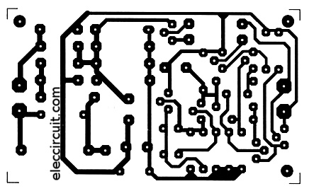
Figure 2 The Copper PCB layout.

Figure 3 The component layout.
Testing
We should check for errors before. The external device as Figure 4. You should be very careful Because we are using the AC 220V directly. When the circuit is correct Then apply AC 220V to the circuit and turns on SW1. You can hear the sirens coming peizo speaker.
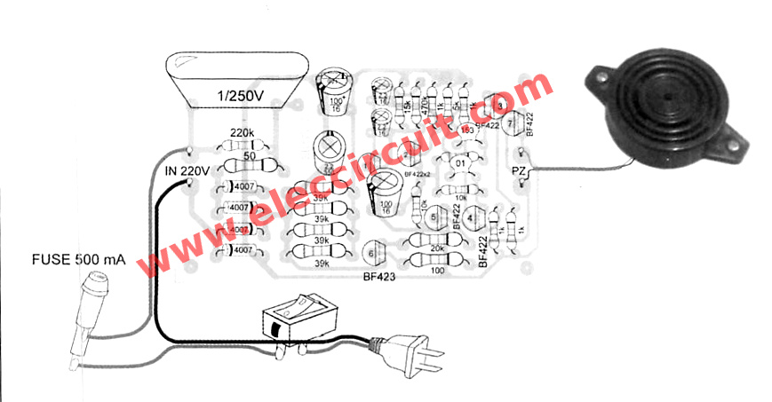
Figure 4 the application.
Components list
Resistor size: 0.25 watt +-5%
R2————–220K
R7————–15K
R8————–470K
R9, R14——–1K
R10, R13——10K
R11————-5K
R12————-33K
Resistor size: 0.5 waitt +- 5%
R1————–50 ohm
R3-R6———39K
R15————20K
R16———–100 ohm
Capacitors
C1————-1uF 250V AC/DC capacitor
C2————-2.2uF 350V_____Electrolyte
C3, C6——–100uF 16V_____Electrolyte
C4, C5——–2.2uF 50V_____Electrolyte
C7————-0.01 uF 50V____Ceramic
Semiconductor
D1-D4———–1N4007____1A 1000V Diode
ZD1————–9.1V 1/2W____Zener Diode
Q1-Q4, Q6-Q7—BF422_____Transistor or similar
Q5—————–BF423_____Transistor or similar
Other parts
FUSE1-Fuse 300mA set ——–1 set.
SW1-Switch AC—————-1 pcs.
PZ1- Piezo Speaker———-1 pcs.
U FB-17——————–1 pcs.
PCB,wires and others
No comments:
Post a Comment